Monday, September 8, 2008
Abstract
Molecular manufacturing should let us synthesize most arrangements of atoms that are consistent with physical law. Assemblers have been proposed as a means for accomplishing this objective (see, for example, Merkle, 1996a). They would be able to build a wide range of useful products as well as copies of themselves. A simpler though less general proposal is a hydrocarbon assembler, restricted to manufacturing relatively stiff hydrocarbons. The design and analysis of such an assembler should be substantially simpler than that of a more general assembler. In this paper, we consider the "intermediary metabolism" of a hydrocarbon assembler, i.e., the set of reactions that permit processing of the feedstock molecules and their conversion into molecular tools (positionally controlled carbenes, radicals, and other reactive species). The specific feedstock molecule analyzed is butadiyne (a linear molecule, C4H2, also known as diacetylene; not to be confused with the more common but chemically distinct non-linear molecule butadiene: C4H6).
Introduction
Most members of the class of stiff hydrocarbons cannot be synthesized today, let alone economically synthesized. More broadly, almost none of the ways that physical law in principle allows us to arrange atoms can be economically achieved with present methods. The objective of the field of molecular nanotechnology is to develop methods which permit the economic synthesis of most structures permitted by physical law. As the direct attempt to achieve this objective might prove difficult, the problem is often broken down into subobjectives and subgoals. One approach is to assume that a general and inexpensive ability to manufacture complex structures with molecular precision can be achieved by using an assembler (Merkle, 1996a). The design of such a device is further broken down into subsystems, and the design and analysis of the subsystems carried out in greater detail. Various aspects of the over all system design can be considered (Drexler 1992, Merkle 1992, 1996a, 1997a, 1997b). This paper focuses on simplifying the set of molecular tools used, and the chemical reactions used to refresh those tools.
A complete analysis of the reactions by which an assembler converts incoming raw materials into reactive tools used to synthesize molecular structures is greatly simplified if we restrict ourselves to the elements hydrogen and carbon, and further restrict our attention to structures that are relatively stiff (excluding, for example, floppy polymers). The stiff hydrocarbons include a wide enough class of materials to be a very attractive goal (diamond, graphite, and structurally related materials are included in this class). Essentially all mechanical structures can be made from stiff hydrocarbons; including struts, bearings, gears, levers, etc. This can be most readily seen by noting that the strength-to-weight ratio of diamond is over 50 times that of steel or aluminium alloys -- a single part made of metal could be functionally replaced by a similarly shaped stiff hydrocarbon part. The resulting part would be lighter and stronger than the part it replaced, improving overall performance. The class of stiff hydrocarbons also includes molecular computers which, by today's standards, would be extraordinarily powerful (Drexler, 1992).
A more general assembler, able to manufacture structures which incorporate most of the elements of the periodic table, would be substantially more difficult to analyze. One approach to breaking down the task of building a relatively large and complex structure would be to consider a series of small incremental changes to an exposed surface, the cumulative effect of which would be to manufacture the whole. This implies we must analyze small changes to the exposed surface, presumably by considering small clusters of atoms on that surface. A very minimal cluster might be a single atom and the atoms to which it is bonded. If one atom is bonded to (say) three neighbors, and all four atoms can be any one of about 100 possibilities, then this gives us 1004 or ~100,000,000 possible clusters. This analysis is crude and likely too small because (a) atoms are often bonded to more than three other atoms and (b) understanding an incremental change to a small cluster often requires examination of atoms farther away than one bond length. Despite its shortcomings, this crude model tells us that we will need to analyze many types of incremental surface modifications before we can reasonably hope to synthesize the full range of structures accessible using this approach.
By contrast, if our structures contain only hydrogen and carbon then the design and analysis problems become much simpler. Hydrogen can only be bonded to one other atom which, if we exclude hydrogen gas, must be carbon. A carbon atom will usually be bonded to two, three, or four neighboring atoms, which can only be hydrogen or carbon. Our previous crude analysis would assign 24 or 16 possible local clusters for carbon. While this can be reduced by considering isomers, it must also be increased to consider interactions that extend beyond a single bond length, e.g., aromatic rings and the like. In any event, the complexities of analyzing hydrocarbon structures with sufficient accuracy for the purposes discussed here is tractable with present capabilities. We cut short the combinatorial explosion before it begins.
While this rather drastic pruning makes the problems of designing and analyzing a hydrocarbon assembler more tractable, it does not directly address the feasibility of more general assemblers. Smalley in particular has argued (Smalley, 1997a) that a "completely universal" assembler is impossible, though he also said (Smalley, 1997b) "Most interesting structures that are at least substantial local minima on a potential energy surface can probably be made one way or another." He argues that a small set of molecular tools will be unable to catalyze all the reactions needed to synthesize the remarkably wide range of structures that are possible. Success will require the use of a great many custom-made catalytic structures.
Given the remarkable size of the combinatorial space of possible molecular structures it does indeed seem likely that at least some members of this space will resist direct synthesis by an assembler equipped with a relatively modest number of molecular tools. However, even if we assume that a substantial percentage of the space is inaccessible via this route (an assumption as yet lacking any clear support) the remaining "small" fraction would include structures of enormous value. Even the ability to manufacture only the highly restricted range of structures defined by the stiff hydrocarbons would usher in a revolution in manufacturing.
Further research aimed at clarifying the range of structures amenable to synthesis by positionally controlled molecular tools seems called for. Ideally, this would include not only the proposal and analysis of particular sets of molecular tools and the range of structures they could reasonably make, but also proposals of structures which could not be synthesized by the use of positionally controlled molecular tools.
One example of an "impossible" structure is a cubic meter of flawless diamond. Before it could be finished, background radiation would have introduced flaws. Drexler argued that it should be possible to define a structure which would be stable if complete but unstable when almost complete, a sort of molecular stone arch (Drexler, 1986, page 246). However, a specific, relatively small, stiff and stable structure that can reasonably be viewed as "impossible" to synthesize using positionally controlled tools has not yet been proposed. While it seems likely that at least some such structures must exist, our understanding of this issue would be greatly improved by specific examples.
An assembler operates in some external environment. While many environments are possible, we consider one specific environment in this paper: a feedstock solution made from the solvent acetone; butadiyne as a source of hydrogen and carbon; neon to support acoustic waves in the interior of the assembler while at the same time not reacting with the highly reactive molecular tools; and a "vitamin" which provides small amounts of elements such as silicon, tin, and one (or more) transition metals -- used basically for catalytic purposes.
Butadiyne (C4H2) seems attractive as a source of hydrogen and carbon for several reasons. The linear structure of butadiyne means that a simple tubular structure, such as a bucky tube, can serve as a suitable binding site to bind butadiyne from the feedstock solution (Merkle, 1997a). As bucky tubes are themselves made of hydrocarbons, a system which can synthesize most hydrocarbons should be able to synthesize the required binding sites. Second, as suggested by the following, relatively simple reactions can be used to convert butadiyne into useful molecular tools. Third, butadiyne has two carbons for every hydrogen. While it's difficult at present to make precise statements about the ratio of carbon to hydrogen in the structural elements of a hydrocarbon assembler, the presence of graphite and relatively thick diamond structures would make carbon significantly more common than hydrogen. As the present proposal uses a single molecule to provide both hydrogen and carbon, a molecule with a relatively high ratio of carbon to hydrogen is desirable (provided other constraints can be met).
By definition, an assembler can make another assembler: they are self replicating (Merkle, 1992, 1994, 1996a). To support self replication it is essential to achieve closure: it must be possible for the assembler to make everything it needs from the feedstock. In this paper, which focuses on the needed molecular tools, we must show that it is possible to generate a new set of molecular tools given only an existing set of molecular tools and a supply of butadiyne. It is not quite sufficient to show that it is possible to make each individual tool given the set of molecular tools and butadiyne. For example, if we could make one dimer deposition tool but used two hydrogen abstraction tools in the process, and we could make one hydrogen abstraction tool but required two dimer deposition tools in the process, then it would be impossible to make a new set of molecular tools from an existing set of molecular tools. The process would "run down hill" until we had exhausted our initial set of tools.
We will first consider how to make each molecular tool, and then consider "quantitative parts closure" in a later section to ensure that it is possible to manufacture a complete set of new tools without depleting an existing set.
Thermal noise
While we do not present an explicit analysis of the effects of thermal noise, some general observations seem in order. Classical positional uncertainty is described by the equation (Drexler, 1992):
(1) sigma2 = kT/ks
where:
- sigma is the mean positional uncertainty (meters, m)
- k is Boltzmann's constant (Joules/Kelvin, J/K)
- T is the absolute temperature (Kelvins, K)
- ks is the stiffness (Newtons/meter, N/m)
Once we know how much positional uncertainty we can tolerate -- and for specific molecular tools that are used to cause specific reactions to occur at specific sites, we can compute the maximum positional uncertainty that can be tolerated before something goes wrong -- then we can design a positional device with the required stiffness. This can be done either by scaling the device size, or by specifying the operating temperature. If we specify room temperature operation then we find that the device size is largely dictated to us. (Drexler, 1992) analyzed this problem and concluded that a robotic arm of about 100 nm (nanometers) in height and 30 nm in diameter and made of diamondoid materials would have a positional uncertainty at room temperature that was a modest fraction of an atomic diameter. (Merkle, 1997b) reached substantially the same conclusions. Stiff hydrocarbons should suffice to make both these and many other positional devices.
To provide a numerical example: if a positional device has a stiffness ks of 10 N/m, then at room temperature (kT ~ 4 × 10-21 J) equation (1) implies a positional uncertainty sigma of 0.02 nm (0.2 Å). The gaussian fall off implies that positional errors of even a few sigma are of very low probability. A properly designed diamondoid positional device should easily be able to achieve a stiffness much higher than 10 N/m. For comparison, the carbon-carbon bond has a stretching stiffness of about 440 N/m.
Put another way, the energy of a system is:
(2) E = 1/2 ks x2
For our example ks of 10 N/m, a 0.154 nm (1.54 Å) deviation (about the length of a carbon-carbon bond) increases the energy of the system by 1.18 × 10⁻¹⁹ J (17 kcal/mol). Such a positional device is very unlikely to make an error as large as a bond length at room temperature.
The molecular tool itself cannot be scaled. A specific molecular tool operated at a particular temperature will have an upper bound on reliability that cannot be improved regardless of how stiff we make the supporting robotic arm. While the molecular tool cannot be scaled, it can be redesigned. The unmodified hydrogen abstraction tool has an estimated lateral stiffness at the carbon atom at its tip of about 6 N/m (Drexler, 1992, figure 8.2). (This tool is long and thin, which is adverse for stiffness). Drexler suggested buttressing the relatively flexible base of the hydrogen abstraction tool, and proposed one redesign which had an estimated stiffness of 65 N/m.
Ultimately, the room temperature reliability of molecular tools suitable for the synthesis of hydrocarbons depends on the achievable stiffness. Existing work suggests that reliable operation at room temperature can be achieved.
Butadiyne
Butadiyne, H-C#C-C#C-H, has a melting point of -36.4°C and a boiling point of 10.3°C. It dissolves readily in acetone. It can polymerize explosively under some conditions. The following information is from (Shostakovskii and Bogdanova, 1974), who provide rules for the safe handling of butadiyne. These include adequate dilution (less than about 30% by volume of butadiyne) and low temperatures (below about 0°C). Mixed 1:1 with butane, liquid butadiyne can be heated to a temperature of 220°C at a pressure of ~1.6 × 10⁷ Pascals (160 atmospheres) "without any danger of explosion." At 25°C and 500 mm Hg the gas showed no evidence of polymerization after 55 days. After three months in a sealed tube at room temperature, a 7.4% solution of butadiyne in acetone showed a "floculent polymer precipitate." Various inhibitors are recommended to prevent polymerization. The heat of solution of butadiyne in acetone is 10.3 Kcal/mole in the temperature range from -40°C to +15°C. Several other solvents could also be used, including butane.
While butadiyne was selected here as the primary feedstock molecule, this choice was motivated by considerations involving the simplicity and ease of analysis of the reactions and the simplicity of the binding site. Other hydrocarbon feedstocks will likely be advantageous when other criteria are used (e.g., ease of bulk production and handling of the feedstock).
A complete set of tools?
We assume that the following tools allow us to build all the stiff hydrocarbons that are needed in a hydrocarbon assembler. This assumption requires further investigation, but appears plausible at the present time. Our objective is therefore to synthesize and refresh the following molecular tools from butadiyne:
- The hydrogen abstraction tool:
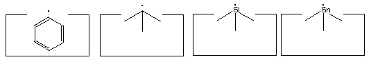
- Two carbon, a silicon and a tin radical:
- Carbenes:
- The dimer deposition tool:
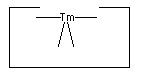
- Positionally controlled transition metal(s):
- The hydrogen deposition tool:
The elevation of the ethynyl radical to the status of "the" hydrogen abstraction tool is based on two main factors. First, it has a higher affinity than almost any other structure for hydrogen. While the H-F bond is stronger than the H-C bond in H-C#C-H, it is unclear how to hold and position a fluorine atom while retaining its high hydrogen affinity. Second, the ethynyl radical has desirable steric properties: it is unencumbered by bulky side groups and and can more easily abstract hydrogens from somewhat less accessible locations.
Many other radicals exist. The group IV radicals -- carbon, silicon, germanium, tin and lead -- seem particularly useful as they can be bonded to three supporting atoms in their radical state. This provides high stiffness and permits relatively large forces to be applied if desired. Group IV radicals also permit selection of radical properties -- the ethynyl radical is the strongest, the phenyl radical -- C6H5 -- is next, followed by the sp3 carbon radical; and then the silicon, germanium, tin and lead radicals in order. Radical properties can be fine tuned by modifying the supporting structures.
Many of the following reactions use one or more radicals. It is often unclear which radical would best serve a particular function. As a consequence, the specific radicals illustrated should be viewed as suggestions: substitution of alternative radicals, particularly other group IV radicals, might well prove advantageous.
Carbenes have proven remarkably useful in the synthesis of organic compounds. Positionally controlled carbenes should be equally if not more useful.
The ability to add two carbon atoms in a single operation using a dimer deposition tool provides more options in adding carbon to a growing structure. (A "dimer" is simply two of something joined together -- in this context, the "dimer" refers to two carbon atoms that are joined together by a triple bond: -C#C- ). While the addition of larger molecular fragments (e.g., polyyne strands, small segments of graphite, etc) will likely prove desirable in many circumstances, the short length of the present paper imposes limits on what we can consider. Future proposals will no doubt consider the advantages of adding larger moieties during the synthesis of hydrocarbons.
The remarkable utility of transition metal catalysts in chemical synthesis rather strongly suggests that positionally controlled transition metals can play a useful role in the synthesis of hydrocarbons. While the present paper uses only a single transition metal it seems likely that more than one will prove useful, particularly as we consider catalyzing a wider range of reactions than the specific ones considered here.
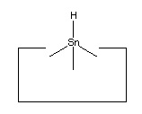
No single proposal is at present accepted as archetypal for the hydrogen deposition tool. Tin is a plausible candidate, as it forms a weak bond to hydrogen. Lead has an even weaker bond to hydrogen and so might prove superior.
We assume that synthesis takes place in an inert environment (vacuum or a noble gas) and that positional control is used throughout. (As the tools are often highly reactive, positional control is essential to prevent undesired reactions). These assumptions permit the use of novel and relatively simple reaction pathways. While the ability to achieve an inert environment using present methods might lead to an attractive implementation pathway, the primary point of the present discussion is to establish that, given a suitable environment, a relatively simple set of reactions and a relatively simple set of molecular tools should be sufficient to let us make the class of stiff hydrocarbons. This class of materials, with a few additions, should be sufficient to let us build some simple assemblers. This class would also let us build environments that would be inert, and in which reactive tools could be deployed with low error rates.
Binding and bonding to butadiyne
 A bucky tube, such as the (9,0) bucky tube illustrated at the right, could serve as a binding site for a simple linear molecule like butadiyne (Merkle, 1997a). Such a binding site would serve to bind the butadiyne from the external feedstock solution, and would allow the transfer of the bound butadiyne to the interior of the assembler.
 Free molecules inside the assembler must be avoided, as their uncontrolled collisions would produce undesired and unpredictable reactions. It is therefore most convenient to bond to butadiyne so that we can control its position and prevent it from uncontrolled encounters with, e.g., the reactive tools discussed here. As there are initially no bonds to the butadiyne it must be held in place by intermolecular forces (predominantly van der Waals and overlap repulsion forces) during the first bonding operation. This paper does not consider in any detail the structure of the site which both positions the butadiyne and makes it accessible to the appropriate molecular tools for the initial bonding operation. We do, however, point out that it is possible to completely surround the butadiyne with a custom-made structure specifically designed to position it during this operation. We also point out that this site will in general be very different from the binding site used to initially bind butadiyne from the feedstock solution.
As there are several tools, there are several candidates for the initial reaction. A carbene could be inserted into any of the bonds. As there are six atoms and five bonds, the carbene could potentially be inserted into any of five positions. There are three positions that are fundamentally distinct: one of the H-C bonds, one of the C#C triple bonds, or the central C-C single bond. Perhaps the most attractive possibility would be to insert a carbene into the H-C bond exposed when the butadiyne first enters the internal environment from its binding site. If the binding site is a bucky tube, then as the butadiyne first exits the bucky tube it could be met with a carbene. A detailed examination of such geometries is necessary to ensure that (1) the carbene will insert into the H-C bond, (2) the carbene will not insert into the adjacent C#C triple bond (despite the attractive electron density provided by the pi bonds) and (3) the butadiyne won't "slip by" and permit bonding in some other (undesired) location or fail to bond at all.
The use of radical additions might be a more attractive approach. As addition of a single radical would (a) permit the butadiyne considerable freedom (it could rotate around the newly formed bond) and (b) result in an open shelled (radical) structure, it would seem preferable to add to the butadiyne with two radicals and form two bonds to it. As we have several radicals to choose from and four carbons and two hydrogens as potential targets, there are many possible specific choices. One choice that seems particularly useful is two silicon radicals adding at the 1 and 4 positions. Following these additions the butadiyne moiety would be well controlled positionally, and we could remove the two hydrogens by applying two hydrogen abstraction tools. These reactions are illustrated below:
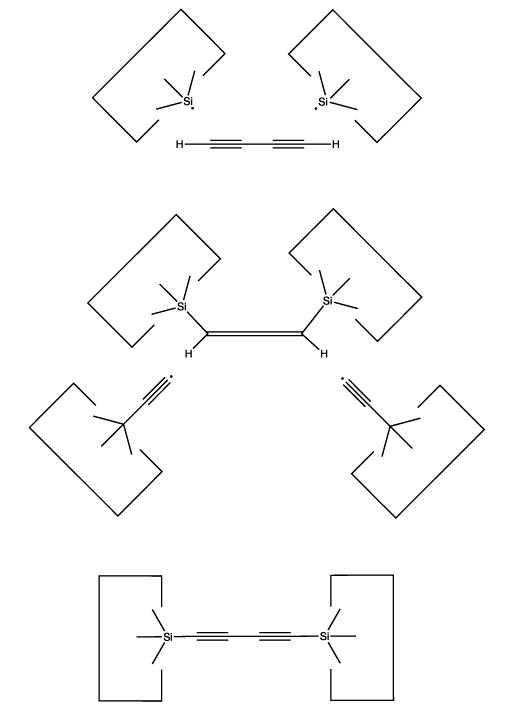
Reactions 1 and 2
Calculations at the 6-311+G(2d,p) Becke3LYP // 6-31G* Becke3LYP level show a barrier height for the addition of a single silicon radical (SiH3) to a terminal carbon of the C4H2 of 14 × 10-21 J (~ 2 kcal/mol). The geometry was optimized at the lower level of theory while a single point calculation at the optimized geometry was computed using the higher level of theory. Calculations were done using the Gaussian B3LYP keyword without zero-point vibrational correction. Details are available on the web at http://www.zyvex.com/nanotech/comp/. The "transition state" was not actually a stationary point on the potential energy surface as rotations of the SiH3 moiety were blocked. (It is possible that the barrier to addition might be an artifact of this constraint). As the SiH3 is supposed to be the tip of a larger tool (which would hinder any rotations), this better models the expected application.
The computed barrier is about three times thermal noise at room temperature, suggesting that the actual barrier for this radical addition is in any event small, and therefore that this reaction will be satisfactory in the present application (especially as activation energy could if necessary be provided by the use of mechanical force).
The use of silicon radicals in this first step permits us to use hydrocarbon structures to confine the butadiyne with less concern that surface hydrogens will be abstracted: the silicon-hydrogen bond is weaker than the carbon-silicon bond. As the radical will have to approach the butadiyne quite closely during the radical addition, and as the hydrocarbon structure confining the butadiyne will also have to be in close proximity to the butadiyne, allowing close proximity between the silicon radical and the confining structure relaxes a significant design constraint.
Another attractive possibility would be the use of two radicals but with different targets: one would attack a terminal hydrogen and the other would attack the adjacent carbon. If both radicals are appropriately positioned then this reaction could take place as the butadiyne emerged from a bucky tube. The result would be to transfer the hydrogen to one radical and the C4H to the other radical.
Saturday, September 6, 2008
Creating and extending the hydrogen abstraction tool
The next step is to create a hydrogen abstraction tool by transferring two carbon dimers to two carbon radicals (either sp2 or sp3 radicals could be used in this step. While the illustrations are suggestive of an sp3 carbon, this is not necessary and might be undesirable in some cases). This is illustrated in the following figure: 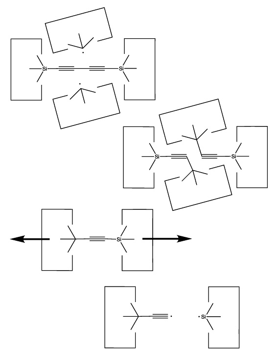
As we sometimes wish to use the dimer at the end of a polyyne as the source of carbon for some other reaction, we need a way to extend the polyyne. This is illustrated below: 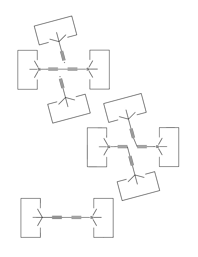
Another useful reaction is the transfer of a dimer from one polyyne to another: 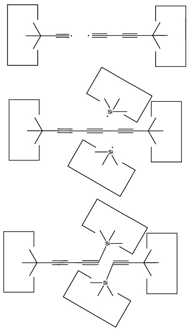
Reactions 3 and 4
Reaction 5
Reaction 6
Reactions 7 and 8
Refreshing the carbene insertion tool
Insertion of a carbene would usually be followed by withdrawal of the tool and detachment of the final carbon. It is therefore necessary to add a carbon to the end of the tool to refresh it. We can transfer a dimer from the end of a polyyne to the end of a cumulene using the following method. First, bond the end of the cumulene and the polyyne. The resulting structure is somewhat schizoid. The left end is a cumulene and the right a polyyne, but where the change takes place is not always clear. We can shift this point by using a silicon radical. We can also weaken the bond we wish to break by using an appropriate transition metal catalyst. Force applied to the ends will now cause the linear carbon sequence to break, presumably at the transition metal. This sequence of reactions is illustrated below: 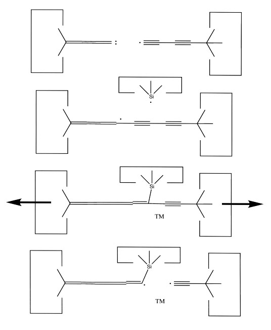
This sequence adds two carbons to the end of the carbene insertion tool, thus refreshing it. If we wish to increase the number of carbene insertion tools (note that we added carbons to a carbene insertion tool, but did not increase their number) we could take the lengthened carbene insertion tools and attach them to a diamond surface: the (100) surface seems particularly attractive for this purpose. Breaking the resulting cumulene would then produce two carbene insertion tools when before there was only one. 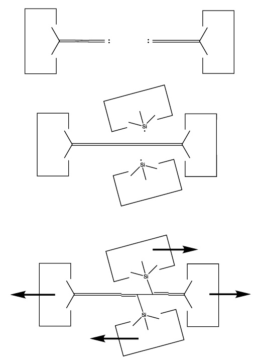
Reactions 9 and 10
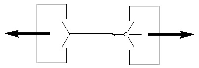
We will sometimes wish to transfer a single carbon atom from the end of one cumulene to another (rather than transferring a dimer consisting of two carbon atoms from a polyyne to a cumulene). Two cumulenes are joined, and then separated. The point of separation is different from the point where they were joined. The point of separation is controlled by the point at which two silicon radicals are applied to the cumulene strand. This is illustrated in the following sequence:
Reactions 11, 12 and 13
Reaction 14
A hydrogen deposition tool
Several of the preceding reactions used a hydrogen abstraction tool (the ethynyl radical). As a consequence, we must refresh this tool without using tools which require the hydrogen abstraction tool for their production. At the same time, we wish to create a hydrogen deposition tool -- a tool with a weakly bonded hydrogen. When used, the hydrogen deposition tool will transfer a hydrogen to a specific site. After use, the hydrogen deposition tool will have to be refreshed by transferring a hydrogen to it. 
This is similar to the proposal by (Drexler, 1992) and simultaneously refreshes both the hydrogen abstraction tool and the hydrogen deposition tool.
The obvious solution to both these problems is to transfer the hydrogen from the abstraction tool to the deposition tool.
As noted earlier, there are many possible structures that would serve as a hydrogen deposition tool. One candidate is tin, which forms a weak bond to hydrogen. One reaction to transfer a hydrogen from the abstraction tool to the depsosition tool is shown:
![]()
Reaction 15
While this reaction is most useful, the tin radical is quite weak. While AM1 suggests that the H-C bond is weakened to 3 × 10-19 J (~45 kcal/mol) by the radical addition, there might still be a barrier to abstraction by tin (and the AM1 estimate might itself be seriously in error, see below). On the other hand, positional control can be used to weaken the H-C bond by, e.g., straightening the C#C-C angle; and can also be used to overcome any barrier by the use of an applied force. It will be necessary to examine this reaction more carefully to determine if transfer of the hydrogen to tin can be performed in one step. If not, the hydrogen could be transferred to a somewhat stronger radical as an intermediate step.
Dealing with excess hydrogen or carbon
As butadiyne provides both carbon and hydrogen in a fixed ratio, it is possible that either (a) there will be an excess of carbon or (b) there will be an excess of hydrogen.
If there is an excess of carbon, then we could build carbon-rich structures. The obvious candidate is graphite. As the present paper is focused on the synthesis of the molecular tools and assumes that it is possible to make diamondoid structures (including graphite) from them, we will not investigate the reactions needed for the synthesis of graphite here.
If we deal with an excess of carbon by building carbon-rich structures and keeping them within the assembler, then we need not design mechanisms for ejecting waste from the assembler. This "zero residue" design is attractive because of its simplicity.
The second possibility is that we have too much hydrogen. In this case, we could build hydrogen-rich structures. Such structures would need to have a higher ratio of hydrogen to carbon than our feedstock molecule, C4H2. Even a 1:1 ratio would suffice, as in hydrogenated graphite. A more attractive structure is polyethylene, which has a ratio of two hydrogens for every carbon. As our feedstock has four carbons for every two hydrogens, one of the four carbons would have to be used in polyethylene to absorb the waste hydrogen (if we assume that no hydrogen at all was used in the actual structures being built). If our assembler was pure carbon (with no hydrogen at all) we would still be able to use three out of every four carbon atoms. As this seems unlikely, we should be able to use more than 75% of the carbon from the feedstock molecule if waste hydrogen is converted to polyethylene.
Strictly speaking, the use of polyethylene violates our stiffness constraint: polyethylene is floppy. The use of hydrogenated graphite does not violate this constraint and still provides a 1:1 ratio of hydrogen to carbon, which is sufficient. It seems likely, however, that many floppy structures can be synthesized with the tools proposed here, and that in many instances this will be convenient. The use of stiff diamondoid "jigs" to constrain the motion of otherwise floppy structures is one approach to their synthesis. Bonding to structures to constrain their motion is another approach. The end of a growing polymer chain could be held in a fixed position with respect to the next monomer to be added, as is done by the ribosome. As polymers are routinely synthesized today, it seems likely that methods for synthesizing them in an assembler are feasible. While convenient, such an ability is not necessary in an appropriately designed assembler, nor in a wide range of useful products that such an assembler could make.
Again, we assume that the synthesis of hydrogen-rich structures is feasible but do not analyze methods for synthesizing specific structures in this paper.
Another approach -- more efficient when large amounts of excess hydrogen are present -- would be to make large bucky balls and store the excess hydrogen inside them as H2 gas. Especially for large spherical bags the ratio of hydrogen stored to carbon used would be very high, as the amount of stored hydrogen would increase as the cube of the size of the bag, while the surface area (and hence the amount of carbon) would increase only as the square. This would eventually be limited by the strength of graphite (a sufficiently large bucky ball made of a single layer of graphite would eventually burst from the pressure) but bucky balls able to contain hydrogen at a pressure of perhaps 108 Pascals (~1,000 atmospheres) with a radius of some hundreds of nm should be feasible.
A third approach would be to generate hydrogen gas and pump it out of the assembler. This seems less desirable, as the hydrogen might reenter through the binding sites designed to bring larger molecules into the assembler. This would require more complex systems (such as the multi-stage cascade proposed by (Drexler, 1992)) to ensure that the interior of the assembler was not contaminated with any H2.
As the production of hydrogen gas inside the assembler cannot be allowed (for example, it would react with the hydrogen abstraction tool and other reactive structures that assume an inert environment) its production would have to be isolated in some fashion from the rest of the assembler. The production of hydrogen gas, although it has advantages, makes the system design more complex. The incorporation of hydrogen into hydrogen-rich structures seems like a simpler approach.
Avoiding excess hydrogen or carbon
We could avoid excess hydrogen or carbon if instead of using a single feedstock molecule to provide both, we used two feedstock molecules -- one of which was hydrogen-rich and the other carbon-rich. Provided that the actual ratio of carbon to hydrogen in a hydrocarbon assembler was between the ratios of these two feedstock molecules, we could avoid any excess of either hydrogen or carbon.
The most hydrogen-rich feedstock molecule is hydrogen gas. For various reasons (discussed earlier) hydrogen gas might not be desirable as a feedstock molecule. An alternative hydrogen-rich feedstock molecule would be methane, which has a sufficiently high ratio of hydrogen to carbon that it seems unlikely that useful hydrocarbon structures would have a higher ratio.
The most carbon-rich feedstock molecule of relatively small size would be some type of buckyball. C60 is the best known. Polyynes terminated by hydrogen are smaller and have a good hydrogen to carbon ratio, but become increasingly unstable as they are made longer.
For the present proposals, we will assume that the 2:1 ratio of carbon to hydrogen in butadiyne is approximately the same as the ratio of these elements in a hydrocarbon assembler. Any excess of either element will be dealt with by building hydrogen-rich or carbon-rich structures, as appropriate, and retaining these structures in the assembler (zero residue).
Friday, September 5, 2008
Quantitative parts closure
In this section we analyze the global use of the proposed molecular tools to make another set of tools. We do this to make sure we don't have a net negative production of some molecular tool, despite a superficial ability to synthesize that tool.
To start the analysis, we note that we can generate as many hydrogen abstraction tools (ethynl radicals) as desired. We start with a set of "spent" hydrogen abstraction tools (i.e., tools with a terminal hydrogen). We also require one functional hydrogen abstraction tool, one spent hydrogen deposition tool (the tin radical) and two silicon radicals. Using reaction 15, we transfer the hydrogen from the tip of the hydrogen abstraction tool to the hydrogen deposition tool. This consumes one hydrogen abstraction tool and one tin radical. We then use a reaction similar to reaction 8 to separate the two hydrogen abstraction tools. This produces two refreshed hydrogen abstraction tools, and leaves the two silicon radicals unchanged.
The net result of these reactions is to transfer a hydrogen from an abstraction tool to a deposition tool, while leaving the rest of the tool count unchanged. Of course, this reaction consumes a tin radical. As we are assuming that the hydrogen deposition tool will be discharged when we manufacture a structure which needs an additional hydrogen, and are further assuming that we can manufacture hydrogen rich structures if this is needed, we will not run out of tin radicals. Put another way, we can get rid of hydrogen by making hydrogen rich structures. When we do this, we remove hydrogens from hydrogen deposition tools. As these tools are simply hydrogen bonded to tin, removing the hydrogen creates tin radicals. This lets us produce as many tin radicals as might be desired.
As we can now refresh the hydrogen abstraction tool at will, we can freely use this tool in the manufacture of other tools. In particular, all other radicals can be generated from their hydrogenated precursors by applying the hydrogen abstraction tool.
Conversion of butadiyne into a bound polyyne (reaction 1 and 2) uses two hydrogen abstraction tools and two silicon radicals. Two additional silicon radicals are used in the production of two C#C dimers able to reload the dimer deposition tool (reaction 21). Loading of the dimer deposition tool results in the bonding together of two silicon radicals. However, these radicals can be regenerated simply by pulling them apart. As a consequence, the net effect of these reactions is to reload two dimer deposition tools with no net decrease in the number of silicon radicals. The two hydrogen abstraction tools used to remove the two hydrogens from butadiyne can be regenerated as discussed earlier.
Generation of carbenes from butadiyne uses only hydrogen abstraction tools, transition metals, and silicon radicals (reactions 9 through 14). The hydrogen abstraction tools are not limiting, and there is no net loss of silicon radicals in this process.
As a consequence, we can freely use all of these tools without concern that they cannot be refreshed. The manufacture of new hydrogen abstraction tools is shown in reactions 3 and 4, while creation of a new carbene insertion tool can be done by attaching a long cumulene to a diamond surface (such as the (100) surface) followed by severing the cumulene as in reactions 12 and 13.
We do not show the detailed synthesis of the positionally controlled transition metal(s), silicon radical or tin radical. As we now have an existing set of tools which we can freely use without concern that they will be irreversibly "used up," the synthesis of the other tools should be feasible. A detailed set of reactions for this process (which would require a specific proposal for the "vitamin" molecule) is needed, but is beyond the bounds of this paper.
Binding sites and feedstock composition
While we could assume a separate binding site for each of the low volume catalytic "vitamins" (e.g., Si, Sn, and the transition metal(s)), it would be easier to consolidate them into a single molecule which consisted of two regions: (1) a heterogenous region which included all required elements: Si, Sn, and the transition metal(s); and (2) a region which could be easily bound by a simple binding site. The latter region might be a simple rectangular planar molecule (as discussing in (Merkle, 1997a)). This single molecule would then be dissected by the molecular tools and converted into the needed positionally controlled catalytic agents. This approach reduces the number of binding sites required, and reduces the problem of designing many binding sites which bind uniquely to their own substrate and do not cross-bind to other substrates. On the other hand, it requires additional steps to convert the "vitamin" into useful structures. As the "vitamin" molecule can presumably be designed to simplify this process, and as it would be necessary to convert precursors into their active form in any event, this approach seems more attractive than the alternative of using a multitude of binding sites each tuned to a specific feedstock molecule.
This leaves us with a feedstock that consists of four main components:
- Acetone (the solvent)
- Butadiyne
- The "vitamin" molecule
- Neon
We can view these four molecules as zero dimensional (neon), one dimensional (butadiyne), two dimensional (the 2-d tab on the vitamin), and three dimensional (acetone). This simplifies the interactions between the binding sites. Molecules of higher dimensionality cannot fit into binding sites of lower dimensionality, while molecules of lower dimensionality will have much lower affinity for binding sites of higher dimensionality. For example, almost nothing will fit into a snug binding site designed for neon. Impurities that can reasonably be expected to enter through a neon binding site are helium and H2. The former is harmless in small amounts, while the latter can be gettered from the external feedstock solution, thus insuring that the concentration of H2 in the feedstock solution is so small that it can be neglected.
In cases where a contaminant of lower dimension has a sufficient affinity for a binding site of higher dimension that it might be a problem, a specific method of eliminating the contaminant will be required. Most generally, the multi-staged cascade approach (Drexler, 1992) could be used. It is reasonable to expect that more special-purpose (and simpler) approaches will be sufficient for the present proposal (e.g., gettering of hydrogen).
Dimer Deposition Tools
While it's often useful to add a single carbon atom to a growing structure by using a carbene, it can sometimes be more convenient to add two carbon atoms at the same time. Such a dimer ( -C#C- )will usually bond readily to two radicals which are separated by an appropriate gap. If, for example, we remove two adjacent hydrogen atoms from the hydrogenated diamond (111) surface, we will have two radicals separated by ~0.25 nm. The use of a carbene to bridge a gap of this size is problematic, but a dimer should bond readily (Walch, 1996). Similar results for the edge of a graphite sheet are plausible. The sequence to deposit the dimer would then proceed as follows. First, the dimer would attach to the surface: 
Following this, the tool would be withdrawn: 
leaving the dimer on the surface. 
This allows the angle and strain of the C-Sn bond to be adjusted to suit the circumstances. The dimer would first be deposited on a suitably prepared site: 
After this, the first Sn moiety could be withdrawn: 
and then the second: 
resulting in deposition of the dimer on the surface, as desired. 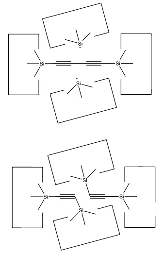
There are many possible dimer deposition tools -- the primary requirement is that the dimer be bonded relatively weakly to the rest of the tool so that after the dimer bonds to the desired target structure removal of the tool results in separation of the dimer from the tool. The general structure of a dimer deposition tool is illustrated below:
Reaction 16
Reaction 17
A more flexible approach would be to form two separately controlled weak bonds to the dimer, as illustrated below.
Reaction 18
Reaction 19
Reaction 20
 A dimer deposition tool similar to a proposal by (Drexler, 1992), is illustrated at the left. This proposal has the useful property that separation of the dimer from its support causes a rearrangement of the bonding structure, thus eliminating any dangling bonds in the tool after the tool is withdrawn. However, it is possible that this dimer will rearrange to the undesired structure illustrated at the right. This issue needs to be investigated further.
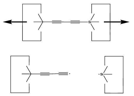
Once the dimer has been deposited on a surface and the tool withdrawn, the tool has been discharged and must be reloaded. Because dimer deposition tools are selected to bind weakly to the dimer (and hence to readily release the dimer when desired), reloading them is energetically unfavorable. In the following sequence we first split a four carbon polyyne chain (as provided by an earlier reaction) into two dimers, bonded at both ends to silicon. We then bend the Si-C#C-Si so that the reaction between it and the discharged dimer deposition tool is energetically favored. The two silicons are then rotated so that they are pointing at each other and force is applied until the approaching silicons form a Si-Si bond and break the Si-C bonds.
Reaction 21
Reaction 22
Reaction 23
Not all proposals will work
 Another proposal for a dimer deposition tool is illustrated at the left. Ab initio calculations at the 6-31G* MP2 level using Gaussian (Frisch, 1995) show all positive vibrational frequencies for the dimer deposition tool, thus implying that it is stable in vacuum at a sufficiently low temperature. AM1 calculations show a barrier between this proposed dimer deposition tool and the isomeric carbene (illustrated at the right) of about 4 × 10-19 J (~60 kcal/mol). Unfortunately, more accurate (and computationally intensive) calculations at the 6-31G* Becke3LYP level show the barrier is only ~6 × 10-20 J (~8 kcal/mol. This does not include zero-point correction), almost an order of magnitude smaller. As a consequence, this dimer deposition tool is unlikely to work reliably at room temperature.
Molecular Manufacturing: Adding Positional Control to Chemical Synthesis
Introduction
Manufactured products are made from atoms. The properties of those products depend on how those atoms are arranged. Viewed from the molecular level today's macroscopic manufacturing methods are crude and imprecise. Casting, milling, welding and all the other traditional manufacturing methods spray atoms about in great statistical herds. Even lithography (which already lets us put millions of transistors on a chip no bigger than your fingernail) is fundamentally statistical and random. Exactly how many dopant atoms are in a single transistor and exactly where each individual dopant atom is located is neither specified nor known: if we have roughly the right number in roughly the right place, we can make a working transistor. For today, that is good enough.The exception is chemistry. Large high purity crystals can have almost every atom in the right place. So, too, can many long polymers. The structures of proteins with hundreds and even thousands of amino acids can be specified down to the last atom. Most dramatically (and fortunately for us!) DNA strands with many tens of millions of bases can be copied with almost perfect accuracy. And it seems that almost any small molecule (with perhaps several dozens of atoms) can be synthesized, if only we have the skill and patience.
Yet the laws of physics and chemistry in principle permit arranging and rearranging the elements in so many combinations and permutations that all of our manufacturing skills and all of our chemical skills barely suffice to scratch the surface of what is possible.
The Utility of Diamond
Almost any manufactured product could be improved, often by several orders of magnitude, if we could precisely control its structure at the molecular level. We often want our products to be light and strong. Diamond is light and strong: the strength-to-weight ratio of diamond is over 50 times that of steel. Yet we do not today have diamond spars in airplanes nor diamond hulls for rockets. Today we can't economically make diamond. Even if we could, simple diamond crystals can shatter. We'd have to modify the structure to make it tough and shatter proof: perhaps diamond fibers. While easily done in principle, we can't do this in practice today.Great strength and light weight are not the exclusive province of diamond: graphite can be stronger. And if we consider the many ways in which carbon atoms can be arranged and rearranged, then it's obvious that there are a host of other possibilities. Yet all share a common problem: we can't yet economically make them in the exact shapes that we want.
Great strength is only one property that we prize highly: when we make computers we are more concerned by electrical properties. Here, too, diamond excels. Today's computers are made of semiconductors, and the semiconductor of choice is silicon. This is not because silicon is the ideal semiconductor from which to make computers, but because we know how to make devices from it. The computer industry has strong opinions about what makes a good logic device and what makes a good computer[1, 2], and diamond will let us make better computers than silicon[3]. Diamond has a wider bandgap, hence electrical devices will work at higher temperatures. It has greater thermal conductivity, so devices can be more easily cooled. It has a greater breakdown field, hence devices can be smaller. It has higher electron and hole mobility which, when combined with higher electric fields, will result in higher speed. But again, we see no diamond computers, just as we see no diamond airplanes: we can't economically manufacture them yet. Large pure crystals of silicon can be made relatively easily, but large pure crystals of diamond are scarce. We can etch the silicon surface and add dopants with a precision measured in tenths of microns, while the corresponding steps for diamond are more difficult. Not more difficult in principle: just more difficult today.
Long Range Complex Order
Making computers highlights another problem. It's not enough to make a pure crystal, it must also have an extremely precise and complex pattern of impurities. The exact location of the dopant atoms in the semiconductor lattice controls how devices function and where signals can propagate. Local order is crucial to make each device work, but long range complex order is crucial to make the computer as a whole work. While we can make some things today that are highly precise and have simple long range order (e.g., crystals), it is the requirement for complex long range order that prevents us from making computers of the kind we'd like to make. While it's plausible we could make high density memory from crystals and perhaps some types of cellular automatons, we couldn't make anything that resembled the computers on the market today. Today's high speed semiconductor-based digital computers (like the 80486 or the Pentium) have millions of logic elements wired together in complex and highly idiosyncratic patterns. This is well beyond the capabilities of crystal growth or bio-polymer synthesis. It will require a fundamentally new manufacturing technology: molecular manufacturing.A Gap
Today, there is a gap in our synthetic abilities: we can make complex mechanical machinery and electronic devices (including computers, which have millions of transistors), but we can't make such devices with the precision with which the chemist can synthesize a crystal, a bio-polymer, or a relatively small molecule. With chemistry we can make precise molecular structures and compounds, but we haven't been able to scale up that success to molecular computers (and other macroscopic products as precise as molecules).Molecular manufacturing will, by definition, let us economically manufacture almost any specified structure that is consistent with the laws of chemistry and physics. To simplify the problem somewhat we can narrow our focus to structures that resemble diamond in a broad sense: the diamondoid structures as defined by Drexler[4]. This class includes (among other things) diamond crystals of arbitrary shape but with stably terminated surfaces (e.g., hydrogenated (111) or the like) and with impurities at precise locations in the diamond lattice (e.g., substitutional boron). Our objective is to manufacture particular diamondoid structures once the location and type of every atom has been specified by design.
The Interest of the Computer Industry
The attraction of molecular manufacturing for the computer industry should be clear. It should let us make computers at a manufacturing cost of less than a dollar per pound, operating at frequencies of tens of gigahertz or more, with linear dimensions for a single device of roughly 10 nanometers, high reliability, and energy dissipation (using conventional methods) of roughly 10^-18 joules per logic operation. If we make thermodynamically reversible computers (which the author and others have recently shown can be made from conventional electronic devices, e.g., CMOS)[5,6,7,8] then the energy dissipation per logic operation can be reduced to well below kT at T = 300 Kelvins (well below 10^-21 joules).The computer industry is spending billions of dollars to make better computers. It is widely acknowledged within the industry that lithography is approaching its limits. Articles like The Future of the Transistor[1], Miniaturization of Electronics and its Limits[9] and Outlook for VLSI: Will the Balloon Burst?[10] quite clearly show that conventional lithography will run out of steam (in perhaps a decade, though there is less agreement about the exact time frame). There is already interest in molecular logic devices[11] and that interest will increase sharply as improvements in conventional manufacturing methods become increasingly difficult. However, any new proposal for manufacturing molecular computers will be weighed against (at least) the criteria mentioned above. If it cannot easily beat conventional methods after they have been pushed to their uttermost limits, then it will be rejected. The computer industry will soon be pouring vast sums into research aimed at molecular computing, but the great bulk of funding will go towards well thought out proposals that offer a realistic possibility of substantially exceeding the performance of the ultimately evolved silicon VLSI technology that we expect to develop over the next decade. If you can't beat tomorrow's mainstream computers, you might as well not try.
The Problem
For this and many other reasons the class of diamondoid structures is a reasonable one to consider. The problem of building a diamondoid electronic computer captures many of the fundamental issues in molecular manufacturing, and poses clearly the issue of building large structures that cannot be made by regular repetition of some substructure (e.g., the unit cell of a crystal or the monomeric unit in a bio-polymer).This brings us to a core issue in molecular manufacturing: how do we synthesize such things?
How We Make Diamond Today
Today, we can synthesize diamond at low pressure and low temperature by using CVD (Chemical Vapor Deposition) methods[12,13]. Diamond CVD growth involves highly reactive species (radicals, carbenes, etc.) in a gas over the growing diamond surface that bombard and react with that surface at random. Because reaction sites are random, growth of many defect structures occurs (dislocations, etc.) as well as the desired perfect diamond structure.Two fundamental mechanisms in the growth process include (1) abstraction of hydrogens from the diamond surface leaving behind reactive sites (dangling bonds, radicals) and (2) interaction of carbon species (both reactive (CH2, CH3, etc.) as well as relatively unreactive species (C2H2)) with the surface, thus depositing carbon.
If we are to synthesize diamondoid structures it is plausible that we begin our search for the basic reaction steps involved in this synthesis by looking at existing reactions that occur in the CVD growth of diamond. The use of a reactive gas in the synthesis process, however, would seem to defeat any hope of making precisely patterned diamondoid structures, for the gas will interact with the growing surface at random.
Positional Control is Fundamental
Here, we introduce the fundamental concept of molecular manufacturing: positional control over the site of reactions. To take a specific example we consider site specific hydrogen abstraction from the diamond (111) surface. The ability to remove specific hydrogen atoms from the surface of the diamondoid work piece under construction is likely to be a fundamental unit operation in any attempt to make atomically precise diamondoid structures.Hydrogen abstraction during CVD diamond growth typically involves a radical reaction between atomic H from the gas with H bonded to carbon on the surface producing H2. It is unclear how to make this process site specific. However, there are other structures with a high affinity for hydrogen which offer greater possibilities for positional control. In particular, the propynyl radical C3H3 (figure 1) has a great affinity for hydrogen. Further, this radical has the very useful property that it has two ends: one end is a highly reactive radical while the other end is a stable sp3 carbon. Thus, we could synthesize a larger molecule with the propynyl radical at its end. The larger molecule would be held at the tip of a positional device. The positional device would provide control over the orientation and position of this hydrogen abstraction tool (e.g., a six degrees of freedom manipulator) and thus control the site of abstraction by controlling the position of the tool.
Figure 1. A site specific hydrogen abstraction tool.
Ab initio quantum chemical analysis of the abstraction of hydrogen from isobutane using an ethynyl abstraction tool supports the idea that the barrier to this reaction is zero[14]. The reaction will proceed rapidly and, because of the large exothermicity, irreversibly. Calculated barriers for abstraction from several other molecules were also small, suggesting that this hydrogen abstraction tool could be used to abstract hydrogen from a wide range of different molecules. Molecular dynamics simulations[14b] provide evidence that the abstraction reaction will select the correct hydrogen atom in the face of thermal noise at room temperature, as well as providing further support for the basic mechanism.
The site specific abstraction of hydrogen illustrates the core concept in molecular manufacturing: selecting the reaction site by controlling the position and orientation of the reactants. The (relatively stiff) diamondoid workpiece is held in place, while a tool (in our example, a hydrogen abstraction tool) is positioned using a rather conventional (if also rather small) robotic arm[15]. The ideas of using tools, controlling the position of those tools with a general purpose manipulator, and building complex structures by putting together components using those positionally controlled tools are rather common and even mundane at the macroscopic level. At the molecular level, they are new and almost shocking: yet it is simply mapping onto the molecular world the concepts and ideas that have proven so useful and powerful in macroscopic manufacturing. By adding positional control we should be able to develop a method of molecular manufacturing which combines the best features of both conventional macroscopic manufacturing and chemical synthesis.
Other Molecular Tools
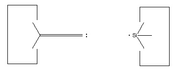
If we are to grow diamond, we must also have carbon deposition tools. Drexler has suggested the use of positionally controlled carbenes (figure 2) and alkynes (figure 3) and proposed reaction pathways and surface structures where these tools would apply[4]. In both cases, the tools are positioned at a precise point on the growing diamondoid structure and are used to deposit one or more carbon atoms at a desired location. These deposition reactions parallel proposals in the CVD literature except for the addition of positional control (e.g., at least one portion of the moiety must be part of an extended "handle" which can be held by a positional device). These are only two examples from the wide range of tools that are capable of depositing carbon on a surface.
Figure 2. A positionally controlled carbene
Figure 3. A positional controlled strained cycloalkyne
The broad range of possible tools coupled with the great power of ab initio computational chemistry should let us define and verify a complete set of molecular tools capable of synthesizing essentially any diamondoid structure. The work by Musgrave et. al.[14] and Sinnott et. al. [14b] are first steps toward this objective. Modern ab initio methods can produce results that are sufficiently accurate for this type of analysis[16, 17]. Further research in this area is feasible and should be pursued.
The Context of Tool Use
For such tools to be usable in a system context we must satisfy certain constraints. First and foremost, we must have a device capable of positioning the tool to within something like an atomic diameter. On the diamond (111) surface, the distance between adjacent hydrogens is about 2.5 Angstroms. Thus, positional accuracy of 1 to 2 angstroms for the hydrogen abstraction tool is required to prevent abstraction of the wrong hydrogen. Second, because the tools can be highly reactive, we require an inert environment. A simple inert environment is vacuum. Compressed helium or some other inert gas would also work. Third, because it is the relative tool-workpiece position that must be controlled, the workpiece under construction must be relatively rigid (e.g., not subject to vibrational motions that would exceed about an angstrom). Fourth and last, we must have some way of generating the sometimes highly reactive tools (e.g., we need to define a precursor to the hydrogen abstraction tool, as well as precursors to the other tools).In some sense, the analysis that we will now pursue is similar in type to retrosynthetic analysis[18]. We start with the final product that we wish to build (a macroscopic diamondoid computer, for example), and then consider the possible predecessor structures which would yield the final product in one step. Then we consider the predecessor structures to those structures, and so on. We extend retrosynthetic analysis beyond its traditional bounds, but the general concept remains the same: given the finished product we deduce the possible ways in which it could have been constructed. This approach has been called "backwards chaining" by Drexler[4].
Positional Devices and Molecular "Arms"
Work with SPMs (Scanning Probe Microscopes)[19] clearly show that it is possible to achieve positional accuracies of a small fraction of an angstrom. Small (~0.1 microns) diamondoid "arms" or positional devices with similar positional accuracy are in principle quite feasible. The field of robotics provides a broad range of designs for positional devices[15] which are largely scale independent. Shrinking these designs to submicron size is conceptually straightforwards. A factor of crucial importance in the design of molecular-scale positional devices is the accuracy with which the tip can be positioned, particularly in the face of thermal noise. While atomically precise bearings and joints will not suffer from chatter, backlash, wear, tooth-to-tooth errors and other sources of inaccuracy caused by imprecise manufacturing[4, 20], they will still suffer from positional errors caused by thermal noise. To control this source of error, it is essential that the robotic arm be very stiff, and so the use of stiff materials is desirable. The Young's modulus for diamond is about 10^12 Pascals (very stiff), and back-of-the-envelope calculations show that a hollow cylinder of such material that is perhaps 100 nanometers long and 30 nanometers in diameter should have a positional accuracy at the tip, in the face of thermal noise at room temperature, of a small fraction of an atomic diameter. A more detailed design and analysis of a jointed tubular robotic arm taking into account the bending and rocking motions of joints in the arm further supports this conclusion[4].Alternatives to the simple robotic arm are available which might be more attractive.
Other Requirements for Tool Use
Creating an inert environment also presents no fundamental problems: high quality vacuums are common in laboratories today. If our objective is to have a very small very high quality vacuum, then a relatively thin wall of diamondoid material could be used as a barrier to keep a volume which was a modest fraction of a cubic micron free of any contaminants. If the volume were initially constructed free of contaminants then such a barrier would keep the inside free of any contaminants with high probability.Because we are building diamondoid structures, they will be very stiff. As a consequence, it is relatively easy to meet the requirement that the objects that are being manufactured must themselves be stiff.
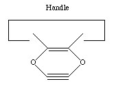
Finally, generation of "activated" tools from relatively stable precursors can be done by a variety of methods. Because we are assuming an environment in which we have positional control we can use particularly simple precursors. We illustrate this by considering a precursor to the hydrogen abstraction tool (see figure 4). This precursor has two handles, and X is chosen so that the X-C bond is weaker than the C-C bond. X might be Si or Ge. If we pull on the two handles with sufficient force, something will break. Because the X-C bond was deliberately selected to be weaker than the other bonds in the structure, it will break. This gives us the activated hydrogen abstraction tool.
Figure 4. A possible precursor to the hydrogen abstraction tool of figure 1.
A related question is: how can we get the hydrogen off the tip of the abstraction tool? A simple answer is: don't. Throw the tool away after one use. In a system design using this approach, it would be necessary to provide a continuous stream of precursors. These would be activated, used once, and then discarded. A more elegant approach would be to remove the hydrogen from the tip and recycle the tool, as discussed by Drexler[4] and Musgrave et. al.[14].
More generally the activation of relatively stable precursors can be done by using any of several forms of energy: mechanical, optical, chemical or other. While the use of mechanical means to provide the activation energy for chemical reactions is relatively novel, in an environment where positional control is already available it is quite natural.
Selective Transport Across a Barrier
Having introduced a diamondoid barrier to keep unwanted contaminants out (much as the bacterial wall allows bacteria to maintain an appropriate internal environment in the face of a fluctuating external environment) we must now solve the problem of getting desired raw materials through the barrier. We might, for example, wish to transport the hydrogen abstraction tool precursor across the diamondoid barrier. After use we will also need to eject the spent tool. Several ways to solve this problem are feasible. A proposal by Drexler is to use a rotor embedded in the diamondoid wall which moves binding sites from the outside of the wall to the inside of the wall (figure 5 [4, page 378]). By modulating the affinity of the binding site so that it will have high affinity for the desired molecule outside the barrier and low affinity inside the barrier, efficient transport across the barrier can be achieved. The desired molecule will bind to the binding site when it is outside the barrier, the binding site will be rotated to the inside of the barrier and the binding affinity reduced (in the illustrated proposal by mechanically pushing a rod into the binding site, thus physically precluding occupancy), and the molecule will be released on the inside of the barrier. The result is to increase the concentration of the desired molecule. A few stages of such a filtration system can achieve extremely high purities. The final stage, rather than ejecting the molecule into a liquid, would deliver the molecule into the inert internal environment in a well defined orientation where it could be further processed. One simple method of further processing would be for the oriented molecule to be directly transferred to the tip of the positional device. 
Figure 5. Selective transport of desired molecules across a diamondoid barrier. (From Nanosystems: molecular machinery, manufacturing and computation)
.Control Signals
Finally, we will need a source of control signals for our molecular arm. One general approach would be to use a molecular computer. We will not consider a particular design for a molecular computer here, it is sufficient to note that many proposals for molecular computation have been considered in the literature and it is generally expected that some type of very small computational device will be feasible in a few decades[4, 11].Summary
This completes our (all too brief) outline of a small device able to manufacture a broad class of diamondoid materials. Basically, the design is driven by the desire to provide the environment needed to synthesize diamond and diamondoid materials using the kinds of reactions that occur naturally during CVD growth of diamond. The device is itself made from diamondoid materials, which means that one such device can manufacture a second such device. This ability to self replicate is crucial in achieving low manufacturing costs. As the reader might appreciate, the design and construction of one such general purpose device might well prove to be a time consuming and expensive undertaking. This cost cannot be justified unless the resulting device has great value. If the device can self replicate then the successful design and development of one such device can be used to build an entirely new manufacturing technology. The manufacturing costs for the second, third, fourth, .... 10^10.... etc. devices will consist largely of the raw materials and energy costs. Thus, a very large R&D cost can (if necessary) be justified.A number of technical issues involved in self replicating systems are discussed in Self Replicating Systems and Molecular Manufacturing [21] while some of the obvious safety issues are discussed in The Risks of Nanotechnology[22].
Bricks Without Vacuum
The major driving force in the previous design was the desire to approach fundamental limits (strength, stiffness, thermal conductivity, electrical characteristics, etc.) in the manufactured products. This in turn implied the use of diamondoid materials, which, when coupled with the known chemistry of CVD diamond synthesis resulted in a high vacuum system with highly reactive intermediates.Relaxing the materials requirements gives us a much wider range of possible structures. In particular, we can consider what is sometimes called "brick" or "building block" based nanotechnology. In this approach we first design a set of molecular building blocks, and then assemble the building blocks by the use of positional control. The ribosome can be viewed as the prototype for this approach. The building blocks are amino acids, and they are linked together by the ribosome to form proteins. Our approach differs in two principle respects: first, we add positional and orientational control over the building blocks in three dimensions, while the ribosome can only build structures that are fundamentally one dimensional (relying on linear structures that spontaneously fold into a particular shape to achieve a degree of control in three dimensions). Second, rather than using relatively floppy polymers, we prefer relatively rigid bricks that can be bonded to each other in a stiff three-dimensional framework.
In general, molecular structures built of bricks will be (a) larger (b) weaker (c) less stiff (d) have poorer thermal conductivity (e) have poorer electrical properties (f) etc. etc. etc. The sacrifice made in materials properties is significant. On the other hand, many bricks can be assembled in more conventional environments (solution), and so we can eliminate the need for vacuum. This greatly simplifies the system. Indeed, with brick-based nanotechnology one can relatively easily envision the synthesis of a set of bricks that can, with the addition of positional control, be assembled into a wide range of structures with the stiffness of (say) wood.
Molecular Manipulators
A conceptually simple and relatively near-term way to achieve some degree of positional control would be to use conventional SPMs. The tips used in current SPM's are usually quite crude, and even when it is possible to make a very fine tip the range of possible structures is very limited (tungsten or some other simple material is generally all that's available). The design of tips for the SPM that incorporate individual molecules specifically synthesized for the purpose is a likely next step, and one that seems essential if we are to make progress in using SPM's to guide chemical reactions in a selective way.Such a "molecular manipulator" should be within reach of today's experimental technology. While the Young's modulus of the things it could make would be substantially inferior to that of diamond, this can be compensated by making them bigger. Scaling laws are such that increasing the size of an object by a factor of 10 also increases its stiffness by a factor of 10, and so reduces the positional inaccuracy from thermal vibration by a factor of 10. If we wish to build a molecular "arm" out of bricks, then to achieve the same positional accuracy as with a diamondoid arm we will have to make the arm bigger -- perhaps several tenths of a micron or more -- but the basic design concepts that were discussed previously for use with a diamondoid arm still hold. We can still position the individual bricks accurately both in position and orientation, we can still build larger structures by putting together many bricks, we can still control the synthesis process by positional means, we can still make a positional device from bricks, etc.
Why pursue such an approach when it can only make relatively inferior materials? There are three primary reasons: (1) it's easier to do (2) it could still make many things that are very valuable by today's standards and (3) such systems could be used to make better systems (e.g., diamondoid systems).
As the reader will appreciate, there are many possible candidates for bricks. Many researchers are already considering the design of molecular building blocks[23], although in most cases they do not consider positional control. Krummenacker discusses several of the issues surrounding the design of molecular bricks intended for assembly via positional control[24]. Adding positional control makes the synthesis of a broad range of molecular structures feasible, but at the same time requires the design and synthesis of a mechanism able to provide such control. The obvious first step is to provide positional control using relatively modest extensions to today's SPMs. The most significant addition is the inclusion of a molecular tip, for today's SPMs typically have a limited range of possible tip structures and are often imprecise at the molecular scale.
Conclusion
The long term goal of molecular manufacturing is to build exactly what we want at low cost. Many if not most of the things that we'll want to build are complex (like a molecular Cray computer), and seem difficult if not impossible to synthesize with currently available methods. Adding programmed positional control to the existing methods used in synthesis should let us make a truly broad range of macroscopic molecular structures. To add this kind of positional control, however, requires that we design and build what amount to very small robotic manipulators. If we are to make anything of any significant size with this approach, we'll need mole quantities of these manipulators. Fortunately, any truly general purpose manufacturing device should be able to manufacture another general purpose manufacturing device, which lets us build large numbers of such devices at low cost. This general approach, used by trees for a very long time, should let us develop a low cost general purpose molecular manufacturing technology.While we have focused in this article on diamondoid structures and molecular computers based on semiconductors such as diamond, it will probably be easier to first make systems that rely on materials that are simpler to synthesize but whose material properties are not as good as diamond. The general concept of positional control, however, still applies. A future article will discuss in greater detail the design of such simpler systems, and how they can form a stepping stone to mature molecular manufacturing.
Many challenges must be met and it will be many years before we develop molecular manufacturing; but the goal is worthwhile, achievable, and offers great rewards both financial and scientific.
Self replication and nanotechnology
A crucial objective of nanotechnology is to make products inexpensively. While the ability to make a few very small, very precise molecular machines very expensively would clearly be a major scientific achievement, it would not fundamentally change how we make most products.
If we are to use positional assembly of molecular parts to efficiently build large structures (kilograms or more) then we will have to use some form of massive parallelism. One robotic arm would take forever to build a kilogram-sized object one molecular part at a time, so we'll need huge numbers of robotic arms working together. One general approach is to follow nature's example and design and build self replicating systems (this is the approach taken by Drexler's assembler: a small device able to manufacture other assemblers as well as valuable products). A different approach is to seek our inspiration from today's factories. This latter approach leads to various forms of convergent assembly. In convergent assembly, parts are assembled using robotic manufacturing systems, and then those (now larger) parts are passed along to other robotic manufacturing systems. Progressively larger parts are handled by progressively larger robotic arms, letting convergent assembly rapidly manufacture large objects (meters in size) starting from small components (nanometers or molecular in size). It seems most likely that some form of convergent assembly will be the dominant approach used in future molecular manufacturing systems. Among other advantages, convergent assembly offers a convenient way to flexibly build large components from small parts. We simply place the parts where we want them to go. Biologically inspired systems use much more indirect methods to form large complex structures, making them less efficient and more difficult to program. On the downside, explaining convergent assembly takes more time. We cannot point to an existing biological example to clarify what we are talking about, but must instead explain a new (and less familiar) manufacturing paradigm. This has slowed understanding of convergent assembly, despite its inherent technical advantages as a manufacturing technology.
This web page focuses on how self replicating systems might be used in manufacturing. If we did not know that such systems existed, many would argue that they were impossible.
Fortunately, we are surrounded and inspired by products that are marvelously complex and yet very inexpensive. Potatoes, for example, are made by intricate molecular machines involving tens of thousands of genes, proteins, and other molecular components; yet the result costs so little that we think nothing of mashing this biological wonder and eating it.
It's easy to see why potatoes and other agricultural products are so cheap: put a potato in a little moist dirt, provide it with some air and sunlight, and we get more potatoes. In short, potatoes are self replicating.
Just as the early pioneers of flight took inspiration by watching birds soar effortlessly through the air, so we can take inspiration from nature as we develop molecular manufacturing systems. Of course, "inspired by" does not mean "copied from." Airplanes are very different from birds: a 747 bears only the smallest resemblance to a duck even though both fly. The artificial self replicating systems that have been envisioned for molecular manufacturing bear about the same degree of similarity to their biological counterparts as a car might bear to a horse.
Horses and cars both provide transportation. Horses, however, can get their energy from potatoes, corn, sugar, hay, straw, grass, and countless other types of "fuel." A car uses only a single artifical and carefully refined source of energy: gasoline. Putting sugar or straw into its gas tank is not recommended!
The machines that people make tend to be inflexible and brittle in response to changes in their environments. By contrast, living biological systems are wonderfully flexible and adaptable. Horses can pick their way along a narrow trail or jump over shrubs; they get "parts" (from their food) in the same flexible way they get energy; and they have a remarkable self repair ability.
Cars, on the other hand, need roads on which to travel; have to be provided with odd and very unnatural parts; are often difficult to repair (let alone self repairing!); and in general are simply unable to cope with a complex environment. They work because we want them to work, and because we can fairly inexpensively provide carefully controlled conditions under which they can perform as we desire.
In the same way, the artifical self replicating systems that are being proposed for molecular manufacturing are inflexible and brittle. It's difficult enough to design a system able to self replicate in a controlled environment, let alone designing one that can approach the marvelous adaptibility that hundreds of millions of years of evolution have given to living systems. Designing a system that uses a single source of energy is both much easier to do and produces a much more efficient system: the horse pays for its ability to eat potatoes when grass isn't available by being less efficient at both. For artificial systems where we wish to decrease design complexity and increase efficiency, we'll design the system so that it can handle one source of energy, and handle that one source very well.
Horses can manufacture the many complex proteins and molecules they need from whatever food happens to be around. Again, they pay for this flexibility by having an intricate digestive system able to break down food into its constituent molecules, and a complex intermediary metabolism able to synthesize whatever they need from whatever they've got. Artificial self replicating systems will be both simpler and more efficient if most of this burden is off-loaded: we can give them the odd compounds and unnatural molecular structures that they require in an artifical "feedstock" rather than forcing the device to make everything itself -- a process that is both less efficient and more complex to design.
The mechanical designs proposed for nanotechnology are more reminiscent of a factory than of a living system. Molecular scale robotic arms able to move and position molecular parts would assemble rather rigid molecular products using methods more familiar to a machine shop than the complex brew of chemicals found in a cell. Although we are inspired by living systems, the actual designs are likely to owe more to design constraints and our human objectives than to living systems. Self replication is but one of many abilities that living systems exhibit. Copying that one ability in an artificial system will be challenge enough without attempting to emulate their many other remarkable abilities.
Complexity of self replicating systems
If our designs are going to be very different from the living systems that inspired us, what approach are we going to follow? The study of artificial self replicating systems was first pursued by von Neumann in the 1940's. Subsequent work, including a study by NASA in 1980, confirmed and extended the basic insights of von Neumann. More recent work by Drexler continued this trend and applied the concepts to molecular scale systems. The author has also contributed a few articles, including: Self Replicating Systems and Low Cost Manufacturing, Self Replicating Systems and Molecular Manufacturing and Design Considerations for an Assembler. (A web page on artificial self replication maintained by Moshe Sipper has links to and information on other references).One conclusion from this body of work is that the design complexity of artificial self replicating systems need not be excessive. One of the simplest "self replicating systems" (when executed, it prints itself out on the standard output) is the following one line C program:
main(){char q=34,n=10,*a="main(){char q=34,n=10,*a=%c%s%c;printf(a,q,a,q,n);}%c";printf(a,q,a,q,n);} (From Self-reproducing programs, Byte magazine, August 1980, page 74. Those interested in a deeper understanding of the recursion theorem and its applications are referred to Introduction to the Theory of Computation by Michael Sipser, 1996, PWS Publishing Company, chapter 6.)
Another conclusion is that "replicating" systems need not be "self replicating." This is best illustrated by exponential assembly, a process by which simple assembly stations on a surface make additional assembly stations on a facing surface. This process provides exponential growth (until the surfaces are fully occupied), but requires extensive non-"self" supporting infrastructure. This is in sharp contrast to biological self replication, where self sufficiency in the replicative process is taken for granted.
The following table illustrates the design complexity of several other systems:
Complexity of self replicating systems (bits)The estimate of the complexity of the internet worm is simply an approximation to the number of bits in the C source code. For the biological systems, the complexity is derived by multiplying the number of base pairs in the DNA times 2. For humans, the number of base pairs is for the haploid, rather than diploid, system. The complexity for the the NASA proposal was taken from Advanced Automation for Space Missions.
Von Neumann's universal constructor ~500,000
Internet worm (Robert Morris, Jr., 1988) ~500,000
Mycoplasma genitalium 1,160,140
E. Coli 9,278,442
Drexler's assembler ~100,000,000
Human ~6,400,000,000
NASA Lunar Manufacturing Facility over 100,000,000,000
Mycoplasma genitalium is the simplest natural living system that can survive on a well defined chemical medium. Its genomic complexity of 1,160,140 bits (twice the 580,070 base pairs sequenced by TIGR) is less than 150 kilobytes -- about one tenth of a typical floppy disk. TIGR is pursuing the Minimal Genome Project to reduce to a minimum the number of genes required for a simple living system. (While viruses are simpler they require a living system to infect: they need additional molecular machinery provided in their environment. For this reason, we exclude them from the table).
The primary observation to be drawn from this data is that simpler designs and proposals for self replicating systems both exist and are well within current design capabilities. The engineering effort required to design systems of such complexity will be significant, but should not be greater than the complexity involved in the design of such existing systems as computers, airplanes, etc. A recent proposal is "Exponential growth of large self-reproducing machine systems," by Klaus S. Lackner and C. H. Wendt, Mathl. Comput. Modelling Vol. 21, No. 10, pages 55-81, 1995.
One last point: self replication is used here as a means to an end, not as an end in itself. A system able to make copies of itself but unable to make much of anything else would not be very useful and would not satisfy our objectives. The purpose of self replication in the context of manufacturing is to permit the low cost replication of a flexible and programmable manufacturing system -- a system which can be reprogrammed to make a very wide range of molecularly precise structures. This lets us economically build a very wide range of products.
Thursday, September 4, 2008
Tools and techniques
The first observations and size measurements of nano-particles were made during the first decade of the 20th century. They are mostly associated with the name of Zsigmondy who made detailed studies of gold sols and other nanomaterials with sizes down to 10 nm and less. He published a book in 1914. He used ultramicroscope that employs a dark field method for seeing particles with sizes much less than light wavelength.
There are traditional techniques developed during 20th century in Interface and Colloid Science for characterizing nanomaterials. These are widely used for first generation passive nanomaterials specified in the next section.
These methods include several different techniques for characterizing particle size distribution. This characterization is imperative because many materials that are expected to be nano-sized are actually aggregated in solutions. Some of methods are based on light scattering. Other apply ultrasound, such as ultrasound attenuation spectroscopy for testing concentrated nano-dispersions and microemulsions.
There is also a group of traditional techniques for characterizing surface charge or zeta potential of nano-particles in solutions. This information is required for proper system stabilzation, preventing its aggregation or flocculation. These methods include microelectrophoresis, electrophoretic light scattering and electroacoustics. The last one, for instance colloid vibration current method is suitable for characterizing concentrated systems.
Next group of nanotechnological techniques include those used for fabrication of nanowires, those used in semiconductor fabrication such as deep ultraviolet lithography, electron beam lithography, focused ion beam machining, nanoimprint lithography, atomic layer deposition, and molecular vapor deposition, and further including molecular self-assembly techniques such as those employing di-block copolymers. However, all of these techniques preceded the nanotech era, and are extensions in the development of scientific advancements rather than techniques which were devised with the sole purpose of creating nanotechnology and which were results of nanotechnology research.
There are several important modern developments. The atomic force microscope (AFM) and the Scanning Tunneling Microscope (STM) are two early versions of scanning probes that launched nanotechnology. There are other types of scanning probe microscopy, all flowing from the ideas of the scanning confocal microscope developed by Marvin Minsky in 1961 and the scanning acoustic microscope (SAM) developed by Calvin Quate and coworkers in the 1970s, that made it possible to see structures at the nanoscale. The tip of a scanning probe can also be used to manipulate nanostructures (a process called positional assembly). Feature-oriented scanning-positioning methodology suggested by Rostislav Lapshin appears to be a promising way to implement these nanomanipulations in automatic mode. However, this is still a slow process because of low scanning velocity of the microscope. Various techniques of nanolithography such as dip pen nanolithography, electron beam lithography or nanoimprint lithography were also developed. Lithography is a top-down fabrication technique where a bulk material is reduced in size to nanoscale pattern.
The top-down approach anticipates nanodevices that must be built piece by piece in stages, much as manufactured items are made. Scanning probe microscopy is an important technique both for characterization and synthesis of nanomaterials. Atomic force microscopes and scanning tunneling microscopes can be used to look at surfaces and to move atoms around. By designing different tips for these microscopes, they can be used for carving out structures on surfaces and to help guide self-assembling structures. By using, for example, feature-oriented scanning-positioning approach, atoms can be moved around on a surface with scanning probe microscopy techniques. At present, it is expensive and time-consuming for mass production but very suitable for laboratory experimentation.
In contrast, bottom-up techniques build or grow larger structures atom by atom or molecule by molecule. These techniques include chemical synthesis, self-assembly and positional assembly. Another variation of the bottom-up approach is molecular beam epitaxy or MBE. Researchers at Bell Telephone Laboratories like John R. Arthur. Alfred Y. Cho, and Art C. Gossard developed and implemented MBE as a research tool in the late 1960s and 1970s. Samples made by MBE were key to the discovery of the fractional quantum Hall effect for which the 1998 Nobel Prize in Physics was awarded. MBE allows scientists to lay down atomically-precise layers of atoms and, in the process, build up complex structures. Important for research on semiconductors, MBE is also widely used to make samples and devices for the newly emerging field of spintronics.
Newer techniques such as Dual Polarisation Interferometry are enabling scientists to measure quantitatively the molecular interactions that take place at the nano-scale.
However, new therapeutic products, based on responsive nanomaterials, such as the ultradeformable, stress-sensitive Transfersome vesicles, are under development and already approved for human use in some countries.
Subscribe to:
Comments (Atom)